Micro:bit accelerometer Introduction

Microbit accelerometer
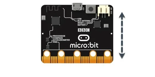
The Micro:bit has a variety of sensors. One of these sensors includes an accelerometer. The accelerometer is behind the B-button. A label on the Micro:bit behind the buttons points to the motion sensor.
The word accelerometer might make you think that it measures acceleration. The accelerometer measures motion. The motion comes from lifting or rotating the Micro:bit.
The accelerometer measures motion in three different directions. It measures motion when the Micro:bit is moved side to side or up and down.
We need a frame of reference when we talk about the motion. Look at the Micro:bit with the contacts facing down. Use the image below as a reference. Place the Micro:bit on a flat surface.
Moving the Micro:bit from left to right is moving along the x-axis.

Moving the Micro:bit up and down is moving it along the y-axis.
Lifting the Micro:bit from the surface is moving it along the z-axis.
The accelerometer measures motion. It measures motion in varying degrees from slight motion to extreme motion. The accelerometer also uses gravity to determine the direction of motion. Motion is not just from side to side or up and down. Rotating the Micro:bit is also considered motion. We are going to focus on rotating the Micro:bit in this lesson.
You don’t need to have a Micro:bit to learn about the Micro:bit. Microsoft provides a free online Micro:bit simulator. No login account is required. Use the link below to access the simulator.
The simulator is also the environment we use to create code for the Micro:bit.
Measuring motion
The best way to understand the motion sensor is to watch it in action.
Click the New Project button.

Use “accelerometer basics” for the project title; click the Create button.

The simulator places two code blocks on the canvas for every new project. The Start code runs code when the Micro:bit starts or is reset. The Forever code is a loop that repeats instructions for as long as the Micro:bit is powered.

We don’t need the [on start] code. Drag it to the code panel.

Select the Basic codes section.

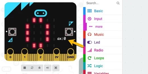
Drag the [Show number] code block and insert it into the Forever loop.

Select the Input section.

Find the [acceleration] code block.

Place the acceleration code block into the [show number] parameter.

The [acceleration] code has three measurement options. Click the Axis selector. The other axis options include the y and z-axis. Leave the selector set to the x-axis.

The simulator shows a big fat zero. The Micro:bit is not moving in any direction. The simulator shows the value for the axis below the B-button.
This is not true in the actual physical Micro:bit.
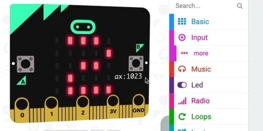
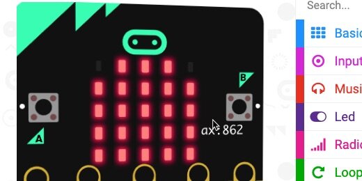
Move your mouse pointer over the Micro:bit simulator; place it over the right edge. The LEDs on the Micro:bit begin to scroll to display the value of the acceleration. The value is also displayed below the B-button. The extreme value and the largest value we can get is 1023.
Move the mouse pointer to the left side of the Micro:bit. The measurement is -1023 at the extreme value.
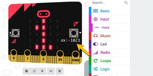
The value 1023 is the largest value we can get when measuring acceleration. This isn’t how fast the Micro:bit has moved. It measures the amount of movement from the center of the Micro:bit when it was laying flat.
Imagine the Micro:bit is laying flat. The image below is in a coordinate plane with x and y-axis lines.

Tilting the Micro:bit to the right increases the motion to the sensor. The measurements go up to a maximum of 1023.

Tilting the Micro:bit to the left increases the motion sensor. This time, the readings are in the negative range from 0 to -1023.

The numbers are represented with negative values because of the coordinate plane. Numbers on the left side of a coordinate plane are negative.
Return to the coding canvas. Select the y-axis in the acceleration code.

Place the mouse cursor over the top center of the Micro:bit. The y-axis value is -1023.

Move the arrow to the bottom center of the Micro:bit. The value is positive.

Move the cursor around the Micro:bit simulator. The numbers displayed range from 0 to 1023 depending on where you place the arrow.
X and Y-Axis measurements
We can get both x and y-axis measurements at the same time. Right-click the [show number] code and select the Duplicate option.

Place the duplicate below the original.
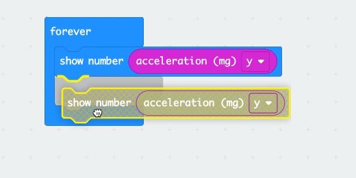
Change the axis of the first to the x-axis.
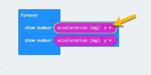
On the simulator, we see information for both the x and y-axis.

Place the mouse arrow over the right edge of the simulator. The Micro:bit displays one value for the x-axis and one for the y-axis.

Accelerometer and input
The accelerometer is an input device. It is also a sensor. It takes information from the surroundings and interprets that information for the Micro:bit to use. We use that interpreted information to react to the input.
Remove both [show number] blocks from the Forever loop.

Go to the LED section and find the [plot bar graph of…] code block.

Place the code block inside the Forever loop.

Go to the Input section and get an [acceleration] code block. Place it into the first parameter.

The bar graph code block creates a bar chart from the information passed into it by the acceleration code. The acceleration code receives information from the sensor. This information is in the form of numbers ranging from 0 to 1023.
The second parameter in the bar graph code block needs the maximum number we want to use in the bar graph. We can choose any number from 0 to 1023. Enter 1023 into the parameter.

Place the pointer over the center of the Micro:bit simulator. Move the arrow to the right, slowly. A bar chart will gradually form and eventually fill the Micro:bit.

Move the pointer to the left side of the Micro:bit. The same chart is created. The chart is created even if the values are negative. The Micro:bit is taking the absolute value of the reading and creating the chart. The absolute value for the readings is positive.

Making decisions
Computers don't think and reason on their own. We can help them make decisions based on the parameters we choose. We will use a condition statement to prevent the Micro:bit from creating a chart when the values are negative.
Go to the Logic section and find the [if True then] code block.

Place the condition code block inside the loop.

Move the [plot bar graph] code block inside the condition block.

The condition statement checks to see if a statement is True or False. The parameter is set to look for a True statement. We need to provide the statement to verify.
Go to the Logic section and find the Comparison operators.

Place the [Less than] comparison operator into the condition parameter.

Click the comparison selector and choose the “Greater Than” option.

Right-click the [acceleration] code and select duplicate.

Place the [acceleration] code into the left parameter of the comparator.

The code explained
The condition compares the value from the accelerator to the number in the right parameter. If the value from the accelerometer is greater than zero, True, then it will run the code in the condition. It will plot the bar graph. If the value is “Less Than” zero, False, then the Micro:bit will not plot the graph. False in this sense means that the value from the accelerometer is not greater than zero.
Test the code
Rotate the Micro:bit to the right; it will plot a bar graph.
Rotate the Micro:bit to the left; it will NOT plot a bar graph.

Acceleration to control Input
The bar graph is plotted as we rotate the Micro:bit. If you rotate the Micro:bit slowly, you will see the graph plotted gradually. We can use the same principle to control almost any input to a program.
The following code uses the [acceleration] code information to control the brightness of the LEDs on the Micro:bit.
Remove the Condition code with the graph plot from the Loop. Set it to one side.

Go to the Basic code section. Get the [show icon] code block and place it into the loop.

Go to the Led section and into the More option. Find the [set brightness] code block.

Connect the [set brightness] code block to the [show icon] code.

Get an [acceleration] code block and place it into the [set brightness] parameter.

Rotate the Micro:bit gradually to the right. The LEDs will get brighter as the number increases. Rotate it to the left and the LEDs will dim. The LEDs do not get bright again if we rotate the Micro:bit to the far left. The brightness code block already understands we can’t brighten something with negative values.