Micro:bit progress bar for data collection projects

Micro:bit progress bar
The Micro:bit has a variety of sensors. Those sensors are an excellent way to collect data for science investigations. The collection of data can take some time. The duration can be a few minutes or more. During that time we don’t have visual clues to provide feedback on the data collection progress.
This is where I decided it would be a good idea to include a progress bar when a Micro:bit is tasked with collecting data. The data can be like a vessel that is filled with a specific amount of information. For example, we might want to collect several measurements as they are coming in from the accelerometer. In another example, we might want to collect the ambient temperature in a room over some time.
The code for this progress bar can be used in a variety of projects. I have a couple of projects in the works where the progress bar will be part of the project.
Programmers often keep libraries of code they can use in a variety of projects or applications. This code will be one of our library resources for use in future projects.
In the lesson, you will learn how to use variables to keep track of information. If you are an educator, you will have the opportunity to demonstrate how math proves to be a useful tool in coding. The project uses basic division, addition, and multiplication. The project refers to the coordinate plane. The coordinate plane is a little different from that used in traditional math, but it does use the same x and y-axis properties.
Use the links below to get a copy of the finished project and the basic progress bar project.
My progress bar(Make Code): https://makecode.microbit.org/_APVgej8KFfW5
My progress bar(Github): https://github.com/digitalmaestro/my-progress-bar
Basic progress bar(Make Code): https://makecode.microbit.org/_8AP8P5546E2i
Basic progress bar(Github): https://github.com/digitalmaestro/a-basic-progress-bar
Micro:bit simulator and Make Code
You don’t need a Micro:bit to follow along in this project. Make Code offers an Integrated Development Environment, IDE, for the Micro:bit. The IDE includes a Micro:bit simulator. Use the link below to access the Make Code website.
https://makdecode.microbit.org
Click the “New Project” button.
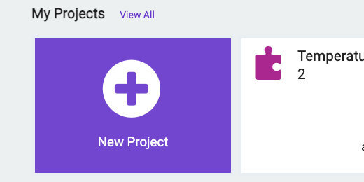
Use “My Progress Bar” for the project name; click the Create button.

A progress bar is based on the measurable completion of a process. The measurement is taken as either a counter toward the completion or as a percentage of the complete process. We are going to use a simple counter to generate the progress bar.
In a project, we are likely to collect a specific number of values from a sensor over a given period. In this example, we are going to use the temperature sensor to collect data. We are going to query the sensor every two minutes. The period can be longer or shorter. The progress bar works the same regardless of the number of values collected.
The Micro:bit has five LEDs across and five down. The five LEDs across will be used to represent the progress bar. The progress bar will light up across the middle of the Micro:bit. The number of values we decide to collect needs to be divided into equal units represented by each of the five LEDs. We can take care of this with a simple division.
To understand how this progress bar works, let's take a look at some examples. We want to take 30 temperature measurements over some time. The time does not matter in this example. We need five markers in those thirty measurements to use for the progress bar. Thirty divided by five is six. An LED will light along the progress bar every time we reach a count that is divisible by six.
While counting we need to compare the count to a marker divisible by six. The table below shows six multiplied by one; then multiplied by two; then three; four; and finally five. The answers for each represent a value we will use to activate one of the LEDs. The first LED will light when the counter reaches six. The second LED will light when the counter reaches 12. The process continues until the counter reaches 30.

The same holds if we choose a different number of sensor readings. In this next example, we are collecting 80 readings. The table shows the divisions and values for each division. Eighty divided by five is sixteen. This number is multiplied by five, then four to one in the table.

The values are different for each number. The difference is not an issue. We are using an algorithm to activate each LED regardless of the value.
The difference between each stage increases as the number of values collected increases. This will trigger each LED to be light for a long time before the next lights. We will take care of this by instructing each LED to blink while data is being collected during each stage.
Go to the Variables section; click the “Make a variable” button.
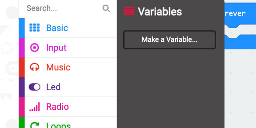
Use “totalCount” for the variable name; click the OK button.

Make another variable; use “unit” for the variable name.
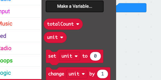
Three code blocks are created for each variable. The first is the variable block itself. The other variables set the value of a variable and change the variable by some value.
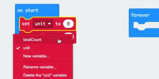
Place the [set variable to] code block into the [on start] section.

Place another [set variable to] code into the [on start] section. Click the variable selector for the first code block and choose the [totalCount] variable. Make sure the second is set to the [unit] variable.
The [totalCount] variable represents the number of values we want to collect from the temperature sensor. Enter 30 in the variable assignment parameter.

The [unit] variable will hold the value when we divide five into the total number of measurements we want to collect. In math, this is referred to as the Quotient. The quotient is part of the pattern of numbers used in the progress bar.
Go to the Math section; find the division operation.

Place the division operation into the [unit] variable parameter.

Get the [totalCount] variable; place it into the left side of the division operator.

Enter the number five into the right side of the operator.

We need another variable. This variable will be used as the container to keep track of the count.
Go to the Variables section; create a new variable. Use “counter” for the variable name. Place the [set counter to] code into the [on start] section.

Go to the Input section; get the [on button A pressed] code and place it on the coding canvas.

We are using a loop to keep track of the readings and values collected. The loop will generate a progress bar as long as the counter is less-than or equal-to the total number of values we want to collect. The number of values is 30 in our current example.
Go to the Loops section; get the [while True do] loop and place it into the [on button A pressed] function.

The [while True do] loop will process the contents of the loop while a condition is True. Our condition will be that the counter is less-than or equal-to the [totalCount] value.
Go to the Logic section; get the less-than comparison code block.

Place the comparison block into the loop parameter.

Click the comparator selector; choose less-than or equal-to.

Get the [totalCount] variable and place it on the right side of the comparison code.

Get the [counter] variable and place it on the left side of the comparison code.

The loop will process the code inside the loop as long as the counter is less-than or equal-to the total count. The total number of readings we want to get from the temperature sensor.
Place the [change counter by 1] variable block into the loop. This adds one to the counter each time the loop cycles.

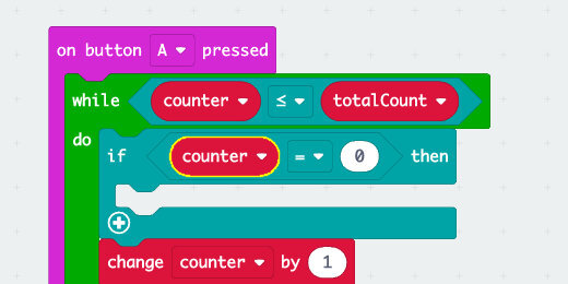
Go to the Logic section; find the [if True then] condition.

Place the condition into the loop. Place it before the [change counter by 1] block.

The code inside a condition is executed if the requirements for the condition are met. The condition needs something to evaluate. One way to evaluate something for a condition is to make a comparison. For example, if something is equal to something else, then run the code in the condition.
Go to the Logic section; get the Equality comparison code block.

Place the comparison code block into the Condition parameter.

Place the [counter] variable into the left side of the Equality comparator.
The other side of the comparison code uses basic math. We need five points to check for comparison. Each is related to one of the LEDs to be light.
In the [on start] section we calculated the units of the division by the 5 segments we need for the LEDs. Multiplying the Unit or quotient(6) by 1, 2, 3, 4, and 5 will generate the markers we need.
Go to the Math section; find the multiplication operation.

Place the multiplication operation on the right side of the comparison code.

Place the [unit] variable into the left side of the multiplication operation.
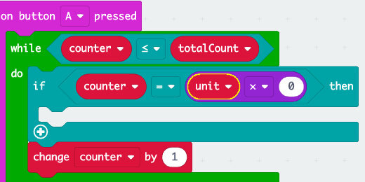
The unit value needs to be multiplied by each number from 1 to 5 for comparison to light each LED in turn. Type the number 1 into the right side of the multiplication operation.

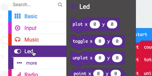
When the counter and the unit values are the same, the first LED will light. Go to the LED section; find the [plot x… y…] code block.
Place the code inside the condition.

The LEDs are numbered using the computer Index. Computer indexes begin with zero. All the LEDs on the Micro:bit begin at index zero from left to right and top to bottom. The LED at index x=0 and y=0 is the top left LED. The progress bar will begin in the third row. This is index zero for the x-axis and two for the y-axis.
Enter the number 2 for the y-axis value.

The LEDs will be light from left to right. The next LED to be light is along the x-axis. The set of index values for the next LED are x=1 y=2. The y-axis index will always be the same.
This is the basis for lighting each of the LEDs in turn. When the counter reaches 12, 6 x 2, the next LED, x=1 y=2, will light.
The numbers for the multiplication and the x-axis index increase by one during each cycle. This is a clue for us to use a counter and a loop.
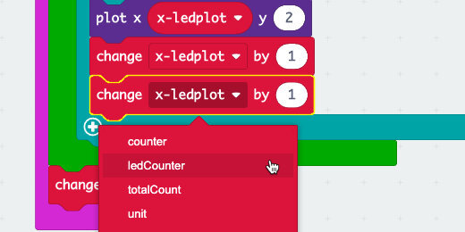
New programmers often want to repeat a process. For example, we could make a copy of the condition statement and change the values for the next LED(don’t do this part). In the image below, I duplicate the condition statement, changed the multiplication value from 1 to 2, and changed the x-axis index to 1. This involves unnecessary repetition of code. If we ever needed to update the code we would need to update each condition. For example, if the next version of the Micro:bit included a 7 by 7 matrix of LED lights. We would need to add two more conditions and change the numbers.

This is what we will do instead.
Go to the Variables section. Create a new variable; use “ledCounter” for the variable name.

Place the [ledCounter] variable on the right side of the multiplication operation.

Place the [set ledCounter to 0] block into the [on start] section.

The [ledCounter] will be used in a multiplication operation. Multiplying anything by zero will result in a zero. There are times when we might want that, but not in this situation. Change the assignment value to number one.

Plotting the LED uses a similar process. We need to change the x-axis index after each LED is light. Go to the Variables section. Create another variable; use “x-ledplot” for the variable name. Place the variable into the x-axis parameter.

Place the [set x-ledplot to] code into the [on start] section.

Place the [change x-ledplot by 1] code into the condition statement. Place the code after the code to plot the LED light. This changes the value after the previous LED is light.

Place another [change variable by] code block into the condition statement. Change the variable to [ledCounter].
Reviewing the code
When the counter matches the markers, the condition statement will run the code inside. Let’s walk through a couple of steps.
The counter will increase by one each time through the loop until it reaches the first marker at six. The LED at the positions x=0 and y=2 will light. The [x-ledplot] variable will increase by one. The [ledCounter] variable will also increase by one.
During the next series of loops, the counter will need to match the product of the Unit variable times two. When the counter matches 12, the LED at positions x=1 and y=2 will light. Each of the variables will increase by one. The process will continue until the counter reaches the value of 30.
One more thing
Move the [change counter by 1] code block; place it after the condition statement and in the loop.

Running the program
The progress bar code is complete. Click the A-button.
The code generated the progress bar but it did so a little too fast. Get a [pause] code block from the Basic section. Place it below the condition statement and before the change counter code block.

More data points
The progress bar works with any number of data points we want to collect. Change the [totalCount] variable with another value. For example, enter 80 and click the A-button.

The progress bar takes a little longer to render. That’s because we are collecting more values between each marker.
Collecting temperature values
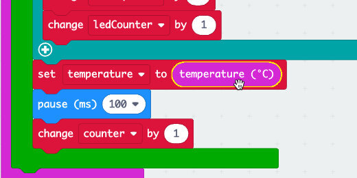
We can add any operation after the pause code. Create a variable; use “temperature” for the variable name.
Place the [set temperature to] code before the pause code.

Go to the Input section. Get the [temperature] code and place it into the [set temperature to] parameter.
Go to the Radio section; find the [radio set group] code.

Place the code into the [on start] section.

Find the [radio send value ] code block.

Place the code block after the [set temperature to ] code.

Change the value name to Celsius.

Get the [temperature] variable; place it into the [radio send value] assignment parameter.

Change the pause value to 1-second.

Change the [totalCount] variable assignment to 30.

This code will collect temperature information. It will get a new reading every second. The reading will be transmitted to another Micro:bit. It will do this for a total of 30 times, 30-seconds. The progress bar will keep track of the process.
Blinking progress
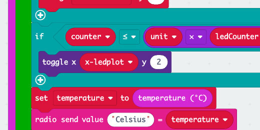
Collecting move information from the sensor requires more time. The progress bar, in turn, takes longer. It could seem like the progress might have stalled. We are going to include a toggle process in the code each time the loop cycles. A toggle will turn the LED Off if it is On or On if it is Off.
Go to the Logic section; get an [if True then] code block. Place the code after the [if True then] in the loop.

We are using a similar comparison to the one used in the condition above. We can copy all the blocks in this comparison. Move your mouse over the code. Look for the comparison code block to be highlighted.

Right-click when the comparison code is highlighted; select the duplicate option.

Get the code and place it into the condition parameter.

Change the Equality operator to less-than or equal-to.

Go to the LED section; get the [toggle x… y…] code block.

Place the code block into the condition statement.

Get the [x-ledplot] variable; place it into the toggle x-axis parameter. Enter two for the y-axis parameter.
Run the program. Each LED in the progress bar will blink until the counter reaches the required value.
We can reuse this code for other projects. All we need to do is replace the information we want to gather.
